PEM.DISC.IPM.03HP.M1
Description:
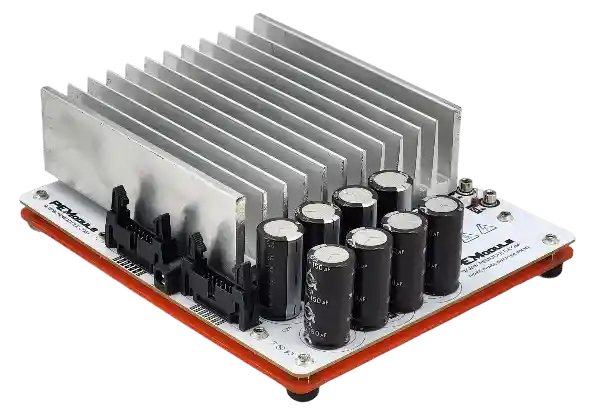
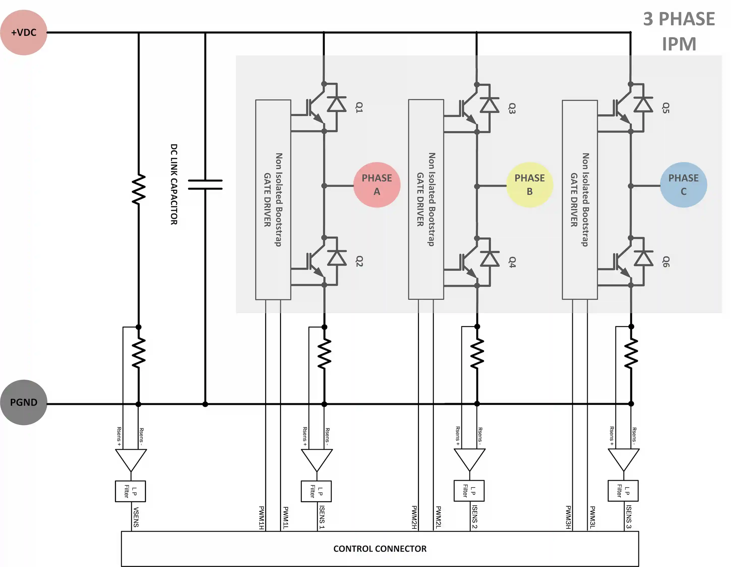
PEModule PLUGY Discovery High-performance cost effective 3HP 2.2KW three phase inverter with voltage and current measurement based on non-isolated IPM technique including DC Link capacitor and protections.
Main Features:
- Compact size.
- High Current Low ESR DC-Link capacitors.
- Overload fuse protection.
- Over voltage varistor protection.
- DC link voltage measurement.
- Including thermal management (no need for external heat sink).
- Including bootstrap gate drivers for all IGBT switches.
- Based on 600V/30A high-performance IGBT.
- Three Legs current measurement.
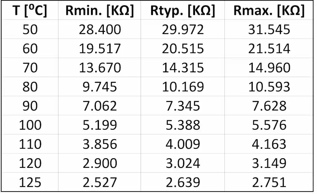
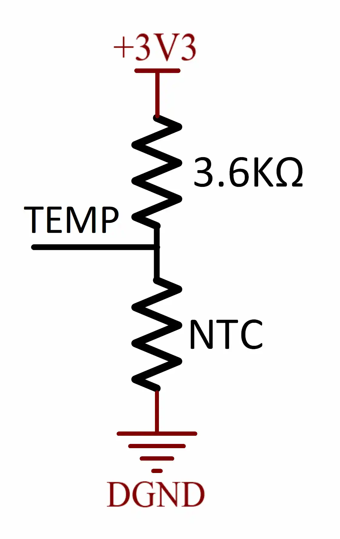
- IPM Temperature measurement.
- Single end control voltage +5VDC only needed.
- PWM signals TTL/CMOS compatible.
Follow us
IPM Module Specifications
IPM Module Specifications
| Parameter | Symbol | Value | Unit |
|---|---|---|---|
| Collector-Emitter voltage (DC link voltage) | VCE | 400 | V |
| Collector Current | IC | 20 | A |
| Collector-Emitter saturation voltage | VCEsat | 2.05 | V |
| Turn-on energy | Eon | 0.96 | mJ |
| Turn-off energy | Eoff | 0.62 | mJ |
| Total switching energy | Etot | 1.58 | mJ |
| Thermal resistance transistor junction to case | RthTJC | 4.13 | C/W |
| Diode forward voltage | VF | 2.6 | V |
| Reverse recovery charge | Qrr | - | uC |
| Reverse recovery time | trr | 50 | ns |
| Switching Frequency | Fsw | 20 | KHz |
| Power Losses Dissipation(Natural Air Convection Model) | PLosses | 40 | W |
| Heatsink thermal resistance | R thHS | 1.77 | C/W |
PWM Connector Pinout
PWM Connector Pinout
| Pin | Symbol | Function |
|---|---|---|
| 1 | +5 VDC | Positive power supply |
| 2,4,6,8,10,12,14 | GND | Ground terminal |
| 13 | PWM1 | PWM input signal TTL or CMOS |
| 11 | PWM2 | PWM input signal TTL or CMOS |
| 09 | PWM3 | PWM input signal TTL or CMOS |
| 07 | PWM4 | PWM input signal TTL or CMOS |
| 05 | PWM5 | PWM input signal TTL or CMOS |
| 03 | PWM6 | PWM input signal TTL or CMOS |
Analog Connector Pinout
Analog Connector Pinout
| Pin | Symbol | Function |
|---|---|---|
| 1 | +5 VDC | Positive power supply |
| 2,4,6,8,10,12,14 | GND | Ground terminal |
| 03 | IDC | Analog output signal for DC link current measurement |
| 05 | TMP | Analog output signal for temperature measurement |
| 07 | IW | Analog output signal for LEG Current Measurement |
| 09 | IV | Analog output signal for LEG Current Measurement |
| 11 | IU | Analog output signal for LEG Current Measurement |
| 13 | VDC | Analog output signal for DC link voltage measurement |
IPM Temperature Sensor
IPM Temperature Sensor
| Current Sensor Equation | Voltage Sensor Equation |
| Isens = I*0.15R*1.8+1.25V | Vsens = Vdc*0.01 |
Follow us!
Follow us!


